目录
点击这里查看所有博文
本系列博客所诉资料均来自合宙官方,并不是本人原创(只有博客是自己写的),csdk只是得到了口头的允许公开授权。出于热心,本人将自己的所学笔记整理并推出相对应的使用教程,方面其他人学习。为国内的物联网事业发展尽自己的一份绵薄之力,没有为自己谋取私利的想法。若出现侵权现象,请告知本人,本人会立即停止更新,并删除相应的文章和代码。
本系列博客基于紫光展锐的RDA8910 LTE Cat 1 bis芯片平台开发。理论上适用于合宙的Air720U、Air724U、广和通L610以及安信可的cat-01模块。
先不管支不支持,如果你用的模块是是紫光展锐的RDA8910,那都不妨一试,也许会有意外收获(也有可能变砖,慎重!!!)。
我使用的是Air724UG开发板,如果在其他模块上不能用,那也不要强怼,也许是开发包不兼容吧。这里的代码是没有问题的。例程仅供参考!
一、前言
拿到CSDK首先搭建好环境,然后就是点灯,点灯才是迈向驱动众多外设的第一步。

有人讲你这真是闲的没事干,拿这个好几百软妹币的模块用来点灯,51它不香吗。小伙子还是年轻,听我一句劝。学习是次要的,最重要是要学会装逼,用51还怎么装逼呢,too young,too simple。

反正我不管你们说什么我都不听,谁也拦不住我,我就是要点灯,今天这个灯我就点定了。

二、编写测试程序
首先我们创建两个任务作为对比
1
2
3
4
5
6
7
8
9
|
int appimg_enter(void *param)
{
osiThreadCreate("GPIO0", GPIO0, NULL, OSI_PRIORITY_NORMAL, 1024, 0);
osiThreadCreate("GPIO1", GPIO1, NULL, OSI_PRIORITY_NORMAL, 1024, 0);
return 0;
}
|
编写GPIO0的输出程序,实现1s为周期的循环闪烁。
1
2
3
4
5
6
7
8
9
10
11
12
13
14
15
16
17
18
19
20
21
22
23
24
25
| static void GPIO0(void *param)
{
T_AMOPENAT_GPIO_CFG output_cfg = {0};
output_cfg.mode = OPENAT_GPIO_OUTPUT;
output_cfg.param.defaultState = 0;
BOOL err = 0;
err = iot_gpio_config(0, &output_cfg);
if (!err)
return;
while (1)
{
iot_gpio_set(0, 1);
iot_debug_print("GPIO0 :%d", 1);
osiThreadSleep(500);
iot_gpio_set(0, 0);
iot_debug_print("GPIO0 :%d", 0);
osiThreadSleep(500);
}
osiThreadExit();
}
|
编写GPIO1的输出程序,实现2s为周期的循环闪烁。
1
2
3
4
5
6
7
8
9
10
11
12
13
14
15
16
17
18
19
20
21
22
23
24
25
| static void GPIO1(void *param)
{
T_AMOPENAT_GPIO_CFG output_cfg = {0};
output_cfg.mode = OPENAT_GPIO_OUTPUT;
output_cfg.param.defaultState = 0;
BOOL err = 0;
err = iot_gpio_config(1, &output_cfg);
if (!err)
return;
while (1)
{
iot_gpio_set(1, 1);
iot_debug_print("GPIO1 :%d", 1);
osiThreadSleep(1000);
iot_gpio_set(1, 0);
iot_debug_print("GPIO1 :%d", 0);
osiThreadSleep(1000);
}
osiThreadExit();
}
|
使用GPIO的驱动需要包含#include "iot_gpio.h"头文件,我们这里只用到了两个函数,分别是:
/*初始化gpio
*@param port: GPIO编号
*@param cfg: 配置信息
*@return TRUE: 成功
FALSE: 失败
*/
BOOL iot_gpio_config(E_AMOPENAT_GPIO_PORT port,T_AMOPENAT_GPIO_CFG *cfg);
/**设置gpio
*@param port: GPIO编号
*@param value: 0 or 1
*@return TRUE: 成功
FALSE: 失败
*/
BOOL iot_gpio_set(E_AMOPENAT_GPIO_PORT port, UINT8 value);
三、编译并下载程序
完整代码在这,自取。
1
2
3
4
5
6
7
8
9
10
11
12
13
14
15
16
17
18
19
20
21
22
23
24
25
26
27
28
29
30
31
32
33
34
35
36
37
38
39
40
41
42
43
44
45
46
47
48
49
50
51
52
53
54
55
56
57
58
59
60
61
62
63
64
65
66
67
68
69
70
71
72
73
74
75
76
77
78
79
80
81
82
83
|
#include "osi_log.h"
#include "osi_api.h"
#include "string.h"
#include "iot_debug.h"
#include "iot_uart.h"
#include "iot_os.h"
#include "iot_gpio.h"
static void GPIO0(void *param)
{
T_AMOPENAT_GPIO_CFG output_cfg = {0};
output_cfg.mode = OPENAT_GPIO_OUTPUT;
output_cfg.param.defaultState = 0;
BOOL err = 0;
err = iot_gpio_config(0, &output_cfg);
if (!err)
return;
while (1)
{
iot_gpio_set(0, 1);
iot_debug_print("GPIO0 :%d", 1);
osiThreadSleep(500);
iot_gpio_set(0, 0);
iot_debug_print("GPIO0 :%d", 0);
osiThreadSleep(500);
}
osiThreadExit();
}
static void GPIO1(void *param)
{
T_AMOPENAT_GPIO_CFG output_cfg = {0};
output_cfg.mode = OPENAT_GPIO_OUTPUT;
output_cfg.param.defaultState = 0;
BOOL err = 0;
err = iot_gpio_config(1, &output_cfg);
if (!err)
return;
while (1)
{
iot_gpio_set(1, 1);
iot_debug_print("GPIO1 :%d", 1);
osiThreadSleep(1000);
iot_gpio_set(1, 0);
iot_debug_print("GPIO1 :%d", 0);
osiThreadSleep(1000);
}
osiThreadExit();
}
int appimg_enter(void *param)
{
osiThreadCreate("GPIO0", GPIO0, NULL, OSI_PRIORITY_NORMAL, 1024, 0);
osiThreadCreate("GPIO1", GPIO1, NULL, OSI_PRIORITY_NORMAL, 1024, 0);
return 0;
}
void appimg_exit(void)
{
OSI_LOGI(0, "application image exit");
}
|
编译成功

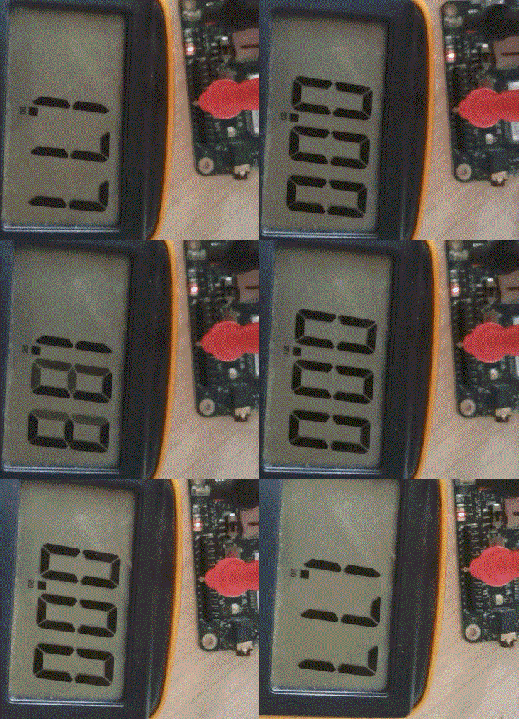
这是GPIO0以1s为周期翻转

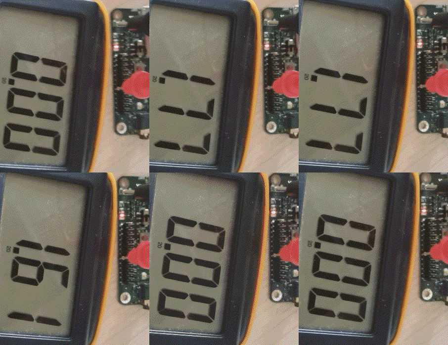
这是GPIO1以2s为周期翻转

查看输出,分析前六个日志,GPIO0的动作是0->1->0->1,GPIO1的动作是0->1,正好GPIO0翻转两次,GPIO1翻转一次,符合设计需求

不会下载的点击这里,进去查看我的RDA8910 CSDK二次开发入门教程专题第一篇博文1、RDA8910CSDK二次开发:环境搭建里面讲了怎么下载
这里只是我的学习笔记,拿出来给大家分享,欢迎大家批评指正,本篇教程到此结束


